Differential motion vectors
The macroblock vector is obtained by adding predictors
to the vector differences indicated by Motion Vector Data (MVD). In case
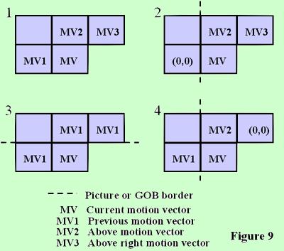
of one vector per macroblock, the candidate predictors for the differential
coding are taken from three surrounding macroblocks as indicated in Figure
9. The predictors are calculated separately for the horizontal and vertical
components.
In the special cases at the borders of the current
GOB or picture, the following decision rules are applied in increasing
order:
1) When the corresponding macroblock was coded in
INTRA mode
(if not in PB-frames mode)
or was not coded (COD = 1), the candidate
predictor is set to zero.
2) The candidate predictor MV1 is set to zero if
the corresponding macroblock
is outside the picture (at
the left side).
3) Then, the candidate predictors MV2 and MV3 are
set to MV1 if the
corresponding macroblocks
are outside the picture (at the top) or outside
the GOB (at the top) if
the GOB header of the current GOB is non-empty.
4) Then, the candidate predictor MV3 is set to zero
if the corresponding
macroblock is outside the
picture (at the right side).
For each component, the predictor is the median
value of the three candidate predictors for this component.
Advantage is taken of the fact that the range of
motion vector component values is constrained. Each VLC word for MVD represents
a pair of difference values. Only one of the pair will yield a macroblock
vector component falling within the permitted range [-16, 15.5]. A positive
value of the horizontal or vertical component of the motion vector signifies
that the prediction is formed from pixels in the previous picture which
are spatially to the right or below the pixels being predicted.
The motion vector is used for all pixels in all four
luminance blocks in the macroblock. Motion vectors for both chrominance
blocks are derived by dividing the component values of the macroblock vector
by two, due to the lower chrominance format. The component values of the
resulting quarter pixel resolution vectors are modified towards the nearest
half pixel position as indicated in Table 15 of the Recommendation H.263.


