Introduction to Motion Estimation and Compensation
Successive video frames may contain the same objects (still or moving). Motion estimation examines the movement of objects in an image sequence to try to obtain vectors representing the estimated motion. Motion compensation uses the knowledge of object motion so obtained to achieve data compression. In interframe coding, motion estimation and compensation have become powerful techniques to eliminate the temporal redundancy due to high correlation between consecutive frames.
In real video scenes, motion can be a complex combination of translation and rotation. Such motion is difficult to estimate and may require large amounts of processing. However, translational motion is easily estimated and has been used successfully for motion compensated coding.
Most of the motion estimation algorithms make the following assumptions:
There are two mainstream techniques of motion estimation: pel-recursive algorithm (PRA) and block-matching algorithm (BMA). PRAs are iterative refining of motion estimation for individual pels by gradient methods. BMAs assume that all the pels within a block has the same motion activity. BMAs estimate motion on the basis of rectangular blocks and produce one motion vector for each block. PRAs involve more computational complexity and less regularity, so they are difficult to realize in hardware. In general, BMAs are more suitable for a simple hardware realization because of their regularity and simplicity.
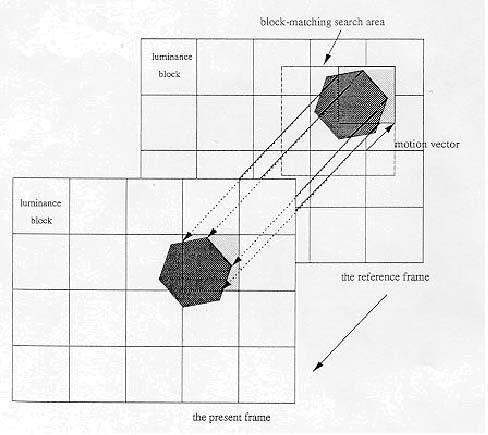
Figure 1.1 illustrates a process of block-matching algorithm. In a typical BMA, each frame is divided into blocks, each of which consists of luminance and chrominance blocks. Usually, for coding efficiency, motion estimation is performed only on the luminance block. Each luminance block in the present frame is matched against candidate blocks in a search area on the reference frame. These candidate blocks are just the displaced versions of original block. The best (lowest distortion, i.e., most matched) candidate block is found and its displacement (motion vector) is recorded. In a typical interframe coder, the input frame is subtracted from the prediction of the reference frame. Consequently the motion vector and the resulting error can be transmitted instead of the original luminance block; thus interframe redundancy is removed and data compression is achieved. At receiver end, the decoder builds the frame difference signal from the received data and adds it to the reconstructed reference frames. The summation gives an exact replica of the current frame. The better the prediction the smaller the error signal and hence the transmission bit rate.
Figure 1.1