![]()
| Introduction | |
| Compression Algorithms | |
| Intra-frame Coding | |
| Inter-frame Coding | |
| Layer and Header Formats |
![]()
Bringing video pictures into the digital era introduces one major problem. Uncompressed digital video pictures take up enormous amounts of information. If you were to record digital video to a CD without compression, it could only hold about five minutes, and that's without any sound ! MPEG reduces the amount of data needed to represent video many times over, but still manages to retain very high picture quality.
MPEG stands for Motion Picture Expert Group, which is established at 1988, consists of some 300 experts take part in MPEG meetings, and the number of people working on MPEG-related matters without attending meetings is even larger.
The MPEG committee which originated the MPEG-1 and MPEG-2 standards that made Digital Television possible, is currently developing MPEG-4 with wide industry participation. MPEG-4 will become Committee Draft in October 1997 and Draft International Standard in December 1998.
The first standard developed by the group, nicknamed MPEG-1, was the coding of the combined audio-visual signal at a bitrate around 1.5 Mbit/s. This was motivated by the prospect that was becoming apparent in 1988, that it was possible to store video signals on a compact disc with a quality comparable to VHS cassettes.
So how does MPEG reduce data by that much and not effect the picture quality? The illusion of movement in TV and cinema pictures is actually created by showing a sequence of still pictures in quick succession, each picture changing a small amount from the one before. We cannot detect the individual pictures - our brain 'smoothes' the action out. A dumb analogue TV picture sends every part of every picture, but digital MPEG video is much smarter. It looks at two pictures and works out how much of the picture is the same in both. Because pictures don't change much from one to the next, there is quite a lot of repetition. The parts that are repeated don't need to be saved or sent, because they already exist in a previous picture. These parts can be thrown out. Digital video also contains components our eyes can't see, so these can be thrown out as well.
Certain sections of video are more complicated than other sections. When there is lots of action and fine detail it's much more difficult to encode properly than a slow moving scene with large areas of the same colour or texture in the picture. MPEG deals with this by concentrating its efforts and data use on the complicated parts. This means that the video is encoded in the best possible way.
MPEG-1, formally known as ISO/IEC 11172, is a standard in 5 parts. The first three parts are Systems, Video and Audio, in that order. Two more parts complete the suite of MPEG-1 standards: Conformance Testing, which specifies the methodology for verifying claims of conformance to the standard by manufacturers of equipment and producers of bitstreams, and Software Simulation, a full C-language implementation of the MPEG-1 standard (encoder and decoder).
Manifold have been the implementations of the MPEG-1 standard: from software implementations running on a consumer-grade PC of today in real time, to single boards for PCs, to the so-called Video CD etc. The last product has become a market success in some countries: in China alone millions of Video CD decoders have already been sold. MPEG-1 content is used for such services as DAB (Digital Audio Broadcasting) and is the standard format on the Internet for quality video.
![]()
In MPEG-1, video is represented as a sequence of pictures, and
each picture is treated as a two-dimensional array of pixels
(pels). The color of each pel is consists of three components : Y
(luminance), Cb and Cr (two chrominance components).
In order to achieve high compression ratio, MPEG-1 must use hybrid coding techniques to reduce both spatial redundancy and temporal redundancy. These techniques are described as the following :
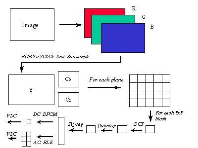
| Color Space Conversion and
Subsampling of Chrominance Information In general , each pels in a picture consists of three components : R (Red), G (Green), B (Blue). But (R,G,B) must be converted to (Y,Cb,Cr) in MPEG-1 ,then they are processed. We can view the color value of each pels from RGB color Space , or YCbCr color Space. Because (Y,Cb,Cr) is less correlated then (R,G,B) , so we can code the (Y,Cb,Cr) components more efficiently. Usually we use (Y,U,V) to denote (Y,Cb,Cr). It's conversion equation is described as below:  After color space conversion, each pels is represented as (Y,Cb,Cr) because human visual system(HVS) is most sensitive to Y component. So we encode Y component with full resolution. But HVS is less sensitive to Cb Cr components, so we subsample Cb Cr components. By doing so we can reduce data without affecting visual quality from person view. In MPEG-1, Y 's resolution is 4 times than Cb's and than Cr's resolution (horizonal 2 and vertical 2), describing as below :and vertical 2), describing as below :  | |
| Quantization Quantization is to reduce a range of numbers to a single small value, so we can use less bits to represent a large number. For example , we can round a real to a integer. That is a kind of quantization. In MPEG-1, use a matrix called quantizer ( Q[i,j] ) to define quantization step. Every time when a pels matrix ( X[i,j] ) with the same size to Q[i,j] come ,use Q[i,j] to divide X[i,j] to get quantized value matrix Xq[i,j] . Quantization Equation : Xq[i,j] = Round( X[i,j]/Q[i,j] ) Inverse Qantization Eqation : X'[i,j]=Xq[i,j]*Q[i,j] Inverse Quantization (dequantize) is to reconstruct original value. But you can see quantization eqation , use Round() function to get a nearest integer value ,so reconstructed value will not the same with original value.The difference between actual value and reconstructed value from quantized value is called the quantization error. In general if we carefully design Q[i,j], visual quality will not be affected. A example of quantization process is described below : Q[i,j]=2 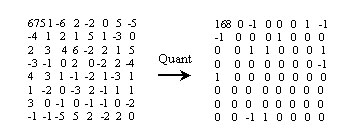 | |
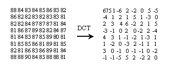
| DCT (discrete cosine
transform) In MPEG-1, we use 8*8 DCT. By using this transform we can convert a 8 by 8 pel block to another 8 by 8 block. In general most of the energy(value) is concentrated to the top-left corner. After quantizing the transformed matrix, most data in this matrix may be zero, then using zig-zag order scan and run length coding can achieve a high compression ratio. Two-dimensional 8x8 DCT transform
u, v, x, y = 0, 1,2, ….,7
Inverse two-dimension 8x8 DCT transform
| |
| Zig-Zag Scan And Run Length
Encoding(RLE) After DCT and quantization most AC values will be zero. By using zig-zag scan we can gather even more consecutive zeros, then we use RLE to gain compression ratio. Below is an zig-zag scan example :  After zig-zag scan, many zeros are together now, so we encode the bitstream as (skip,value)pairs,where skip is the number of zeros and value is the next non-zero componet. you must notice that zig-zag scan and RLE are only used in AC coefficient. But for DC coefficient we apply the DPCM (will be descibed in the next section) coding method. Below is an example of RLE : The value 168 is DC coefficent , so need not to code it. EOB is the end of block code defined in the MPEG-1 standard. 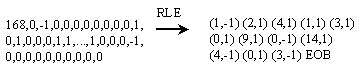 | |
| Predictive Coding Predictive coding is a technique to reduce statistical redundency. That is based on the current value to predict next value and code their difference (called prediction error). If we predict next value more precisely, then the prediction error will be small. So we can use less bits to encode prediction error than actual value. In MPEG-1, we use DPCM (Difference Pulse Coded Modulation) techniques which is a kind of predictive coding. And it is only used in DC coefficient. Below is an example : 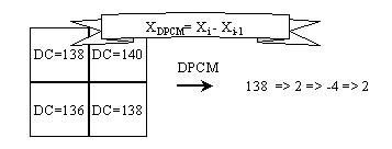 | |
| Motion Compensation (MC)
And Motion Estimation (ME) Motion Estimation is to predict a block of pels' value in next picture using a block in current picture. The location difference between these blocks is called Motion Vector. And the difference between two blocks is called prediction error. In MPEG-1, encoder must calculate the motion vector and prediction error. When decoder obtain these information , it can use this information and current picture to reconstruct the next picture. We usually call this process as Motion Compensation. In general, motion compensation is the inverse process of motion Estimation. Following is an example : 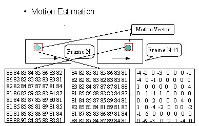  | |
| Variable Length Coding
(VLC) Variable Length Coding is a statistical coding technique. It uses short codeword to represent the value which occurs frequently and use long codeword to represent the value which occurs less frequently. With this method can make the code string shorter than the original data. In MPEG-1, the last of all encoding processes is to use VLC to reduce data redundency and the first step in decoding process is to decode VLC to reconstruct image data. Encoding and decoding processes with VLC must refer to a VLC code table. This code table has two entries. One is original data and the other is the corresponding codeword. In MPEG-1 standard , many different VLC code tables are defined. You can find them in MPEG-1 Standard 2-ANNEX C. Using multiple VLC code tables is to improve compression ratio of VLC. |
![]()
1. Overview
In MPEG-1 Standard, I-Picture is being coded by intra-frame coding. When encoding I-Picture, we only reduce the spatial redundency in the picture without referencing other pictures. The coding process is much similiar to JPEG Standard. So encodig I-Pcture is less complex than P-frame and B-frame. Decoding I-Picture is inverse process of encoding process, so this section we only describe encoding process. Before we go further, we must know the basic coding unit is a block which is a 8 by 8 matrix. And a macroblock is consists of six block: 4 block of luminance (Y) , one block of Cb chrominance, and one block of Cr chrominance. Below is macroblock structure:
2. I-Picture Encoding Flow Chart
3. I-Picture Encoding Process
| Decomposing image to three components in RGB space | |
| Converting RGB to YCbCr | |
| Dividing image into several macroblocks (each macroblock has 6 blocks , 4 for Y, 1 for Cb, 1 for Cr) | |
| DCT transformation for each block | |
| After DCT transform , Quantizing each coefficient | |
| Then use zig-zag scan to gather AC value | |
| Use DPCM to encode the DC value, then use VLC to encode it | |
| Use RLE to encode the AC value, then use VLC to encode it |
4. Conclusion
I-Picture coding is like JPEG standard. By using this, picture can get good quality but compression ratio is low. So we must use another coding method to code picture like intra-frame coding (Will be described in the next section).
This section describes the I-Picture coding process, but not in full details. If you want to implement this encoding process or decoding process you must refer to the MPEG-1 Standard for complete details.
![]()
The kind of pictures that are using the intra-frame coding technique are P pictures and B pictures. We will now discuss how these pictures are coded.
Coding of the P pictures is more complex than for I pictures, since motion- compensated macroblocks may be constructed. Ther difference between the motion compensated macroblock and the current macroblock is transformed with a 2-dimensional DCT giving an array of 8 by 8 transform coefficients. The coefficients are quantized to produce a set of quantized coefficients. the quantized coefficients are then encoded using a run-length value technique.
As in I pictures, the encoder needs to store the decoded P pictures since this may be used as the starting point for motion compensation. Therefore, the encoder will reconstruct the image from the quantized coefficients.
In coding P pictures, the encoder has more decisions to make than in the case of I pictures. thee decisions are: how to divide the picture up into slices, determined the best motion vectors to use, decide whether to code each macroblock as intra or predicted, and how to set the quantizer scale.
| Selection of Macroblock Type There are 8 types of macroblock in P pictures. |
| Motion Compensation Decision The encoder has an option on whether to transmit motion vectors or not for predictive-coded macroblocks. |
| Intra/Non-intra Coding Decision |
| Coded/Not Coded Decision After quantization, if all the coefficients in a block is zero then the block is not coded. |
| Quantizer/No Quantizer Decision Quantizer scale can be altered which will affect the picture quality. |
B pictures are divided into slices in the same way as I and P pictures. Since B pictures are not used as a reference for motion compensation, errors in B pictures are slightly less important than in I or P pictures. Consequently, it might be appropriate to use fewer slices for B pictures.
| Selection of Macroblock Type There are 12 types of macroblock in B pictures. Compare with P pictures, there are extra types due to the introduction of the backward motion vector. If both the backward and backward motion vectors are present, then motion-compensated macroblocks are constructed from both previous and future pictures, and the result is averaged to form the "interpolated" motion-compensated macroblock. |
| Selecting Motion Compensation Mode |
| Intra/Non-Intra Coding |
| Coded/Not Coded Decision |
| Decomposing image to three components in RGB space | |
| Converting RGB to YCbCr | |
| Perform motion estimation to record the difference between the encoding frame and the reference frame stored within the frame buffer | |
| Dividing image into several macroblocks (each macroblock has 6 blocks , 4 for Y, 1 for Cb, 1 for Cr) | |
| DCT transformation for each block | |
| Quantizing each coefficient | |
| Use zig-zag scan to gather AC value | |
| Reconstruct the frame and store it to the frame buffer if necessary | |
| DPCM is applied to encode the DC value, then use VLC to encode it | |
| Use RLE to encode the AC value, then use VLC to encode it |
Inter-frame encoding is used to reduce the encoded bitrate while maintaining an acceptable picture quality by coding the pictures with respect to the previous encoded picture and sometimes the subsequent picture. This kind of encoding achives a much higher compression ratio than the intra-frame coding used in the I pictures. However, one of the drawback is that the encoding process is more complicated.
This section briefly outlines how P pictures and B pictures are coded, for details in implementing them please refer to the MPEG-1 standard.