Computer Organization and Structure
Homework #4
Due: 2005/12/20
1.
Consider two different implementations, I1 and
I2, of the same instruction set. There are three classes of instructions (A, B,
and C) in the instruction set. I1 has a clock rate of 6GHz, and I2 has a clock
rate of 3GHz. The average number of cycles for each instruction class on I1 and
I2 is given in the following table:
|
Class |
CPI
on M1 |
CPI
on M2 |
C1
Usage |
C2
Usage |
C3
Usage |
|
A |
2 |
1 |
40% |
40% |
50% |
|
B |
3 |
2 |
40% |
20% |
25% |
|
C |
5 |
2 |
20% |
40% |
25% |
The table also
contains a summary of average proportion of instruction classes generated by
three different compilers. C1 is a compiler produced by the makers of I1, C2 is
produced by the makers of I2, and the other compiler is a third-party product.
Assume that each compiler uses the same number of instructions for a given
program but that the instruction mix is as described in the above table. Using
C1 on both I1 and I2, how much faster can the makers of I1 claim I1 is compared
to I2? Using C2, how much faster can the makers of I2 claim that I2 is compared
to I1? If you purchase I1, which compiler would you use? If you purchased I2,
which compiler would you use? Which computer and compiler would you purchase if
all other criteria are identical, including cost?
2.
Suppose we have a floating-point unit that
requires 400 ps for a floating-point
add and 600 ps for a floating-point multiply, not including the time to get the instruction or read and write
any registers, which take the same as for an integer instruction. Assume that the functional unit times are the following:
l
Memory units: 200ps
l
ALU and adders: 100ps
l
Register file (read or write): 50ps
Assume the
following:
l
All loads take the same time and comprise 30% of
the instructions.
l
All stores take the same time and comprise 15%
of the instructions.
l
R-format instructions comprise 25% of the mix.
l
Branches comprise 10% of the instructions, while
jumps comprise 5%.
l
FP add and subtract take the same time and
together total 5% of the instructions.
l
FP multiply and divide take the same time and
together total 10% of the instructions.
Find (a) the time for the FP
operations, (b) the time for the processor with a single clock
cycle length equal to the longest instruction, and (c) the time for the processor with a varying
length clock.
3.
We wish to add the instructions jr (jump register), sll (shift left
logical), lui (load upper immediate), and a variant of the lw (load word) instruction to the single-cycle
datapath. The variant of the
lw instruction increments the index register
after loading word from memory. This instruction (l_inc) corresponds to the following two instructions:
lw $rs, L($rt)
addi $rt,
$rt, 1
Add any
necessary datapaths and control signals to Figure 1 and show the necessary additions to Table 1. You can photocopy Figure 1 and Table 1 to make it faster to show the additions.
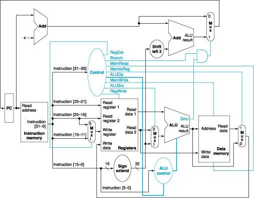
Figure
1: The simple
datapath with the control unit.
|
Instruction |
RegDst |
ALUSrc |
Memto |
Reg |
Mem |
Mem |
Branch |
ALUOp1 |
ALUOp0 |
|
R-format |
1 |
0 |
0 |
1 |
0 |
0 |
0 |
1 |
0 |
|
lw |
0 |
1 |
1 |
1 |
1 |
0 |
0 |
0 |
0 |
|
sw |
X |
1 |
X |
0 |
0 |
1 |
0 |
0 |
0 |
|
beq |
X |
0 |
X |
0 |
0 |
0 |
1 |
0 |
1 |
Table
1: The setting
of the control lines is completely determined by the opcode fields of the
instruction.
4.
We wish to add the instructions lui (load upper immediate) and ldi (load immediate) to the multicycle datapath,
respectively. The ldi instruction
loads a 32-bit immediate value from the memory location following the
instruction address. Use the same structure of the multicycle datapath of Figure 2 and show the necessary modifications to the
finite state machine of Figure 3. How many cycles are required to implement this
instruction?
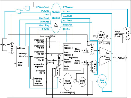
Figure
2: The complete datapath for the multicycle
implementation together with the necessary control lines.
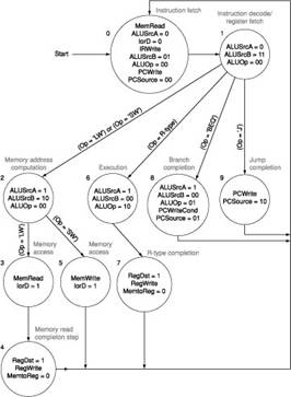
Figure
3: The complete finite state machine control for
the datapath shown in Figure 2.