Computer Organization and Structure
Homework
#4
Due:
2008/12/9
1. Describe
the effect that a single stuck-at-n fault (i.e., regardless of what it
should be, the signal is always n, where n = 0 or 1) would have
for the signals in the following sub-questions:
a.
For single stuck-at-0 fault, which
instructions, if any, will not work correctly in the single-cycle
datapath as shown in Figure 1? Explain why.
Consider each of the following faults separately:
① RegWrite
= 0
② ALUop0
= 0
③ ALUop1
= 0
④ Branch
= 0
⑤ MemRead
= 0
⑥ MemWrite
= 0
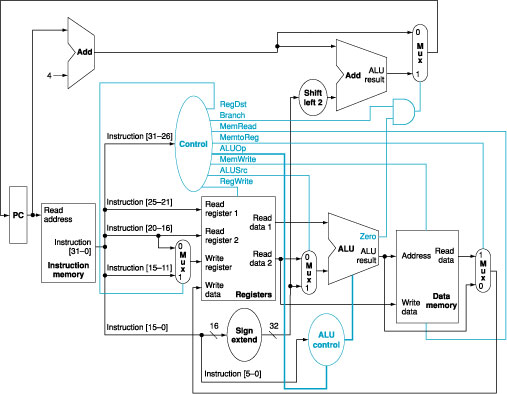
Figure
1: The simple datapath with the
control unit.
b.
For single stuck-at-1 fault, which
instructions, if any, will not work correctly in the single-cycle
datapath? Explain why.
c.
For single stuck-at-0 fault, which
instructions, if any, will not work correctly in the multiple-cycle
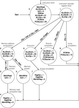
datapath as shown in Figure 2? Explain why.
Consider each of the following faults separately:
a) RegWrite
= 0
b) MemRead
= 0
c) MemWrite
= 0
d) IRWrite
= 0
e) PCWrite
= 0
f) PCWriteCond
= 0
Figure
2: The multicycle
datapath with the control lines.
d.
For single stuck-at-1 fault, which
instructions, if any, will not work correctly in the multiple-cycle datapath?
Explain why.
2. MIPS
chooses to simplify the structure of its instructions. The way we implement
complex instructions through the use of MIPS instructions is to decompose such
complex instructions into multiple simpler MIPS ones. Show how MIPS can implement
the instruction swap $rs, $rt,
which swaps the contents of registers $rs and $rt. Consider the case in which there is an
available register that may be destroyed as well as the care in which no such
register exists. If the implementation of this instruction in hardware will
increase the clock period of a single-instruction implementation by 10%, what
percentage of swap operations in the instruction mix would recommend
implementing it in hardware?
3. We
wish to add the instructions jr
(jump register), sll
(shift left logical), lui
(load upper immediate), and a variant of the lw (load word) instruction to
the single-cycle datapath. The variant of the lw instruction increments the index register after
loading word from memory. This instruction (l_inc) corresponds to the following two instructions:
lw $rs, L($rt)
addi $rt,
$rt, 1
Add
any necessary datapaths and control signals to Figure 1 and show the
necessary additions to Table 1. You can
photocopy Figure 1 and Table 1 to make it
faster to show the additions.
|
Instruction |
RegDst |
ALUSrc |
Memto |
Reg |
Mem |
Mem |
Branch |
ALUOp1 |
ALUOp0 |
|
R-format |
1 |
0 |
0 |
1 |
0 |
0 |
0 |
1 |
0 |
|
lw |
0 |
1 |
1 |
1 |
1 |
0 |
0 |
0 |
0 |
|
sw |
X |
1 |
X |
0 |
0 |
1 |
0 |
0 |
0 |
|
beq |
X |
0 |
X |
0 |
0 |
0 |
1 |
0 |
1 |
Table
1: The setting of the control
lines is completely determined by the opcode fields of the instruction.
4. Show
how the jump register (jr)
instruction can be implemented simply by making changes to the finite state
machine shown in Figure 3. (It may help
you to remember that $0=$zero=0.)
Figure
3: The complete finite state
machine control for the datapath shown in Figure 2.